Gallery 5 Prong Relay Wiring Diagram Fresh 4 Pin Electrical Outlet 5
1. Thinner cables can be used to connect the control switch to the relay thereby saving weight, space and cost. 2. Relays allow power to be routed to a device over the shortest distance, thereby reducing voltage loss. 3. Heavy gauge cable only needs to be used to connect a power source (via the relay) to the device. Why Use a Relay in a Car?

45 Beautiful 5 Pin Relay Wiring Diagram
Want to Design a Relay Wiring Diagram? EdrawMax Circuit Diagram Maker is able to create circuit diagrams and more electrical diagrams, as well as wiring diagrams in minutes. Give it a try! Switch to Mac > Try It Free Here is the most comprehensive guide you can learn about relay wiring diagrams.
Bosch Relay Wiring Diagram 5 Pole Manual EBooks 5 Prong Relay
Relay wiring diagrams are an essential tool in any electrical project. They allow you to visualize and understand the circuit's operation, and provide a quick way to troubleshoot any issues that might arise. Yet, many people find them confusing.

50732 Relay Wiring Diagram
In a "ladder" diagram, the two poles of the power source are drawn as vertical rails of a ladder, with horizontal "rungs" showing the switch contacts, relay contacts, relay coils, and final control elements (lamps, solenoid coils, motors) drawn in between the power rails. Ladder Diagram Symbols

40 Amp Pin Relay Wiring Diagram ubicaciondepersonas.cdmx.gob.mx
Step 1: Wiring Arduino and the relay board. 1) Take a jumper (Dupont cable) and connect one end to PIN 7 of Arduino. 2) Connect the other end of the jumper to the S PIN on the relay module. The connection will look like the image below. 3) Make a connection between Arduino 5 V pin and the (+) PIN on the relay module.
How To Wire A Relay Electrical The Mini Forum
[1] If you're unsure you have the right relay, confirm what type you need at a car dealership, auto shop, or with a mechanic. [2] Confirm whether you need an SPST or SPDT relay and whether the large circuit needs to be normally open (NO) or normally closed (NC) when the relay is at rest.

5 Pin Relay Wiring Diagram Fuel Pump
Relay Wiring Diagram What is a Relay? As mentioned earlier, a relay is essentially a switch. Unlike a traditional switch, which we flip or toggle to make it ON and OFF, a relay is an electromechanical switch. The 'mechanical' action of moving the switch between ON and OFF positions is achieved by an 'electrical' signal.
Wiring Diagram For 11 Pin Relays Wiring Diagram
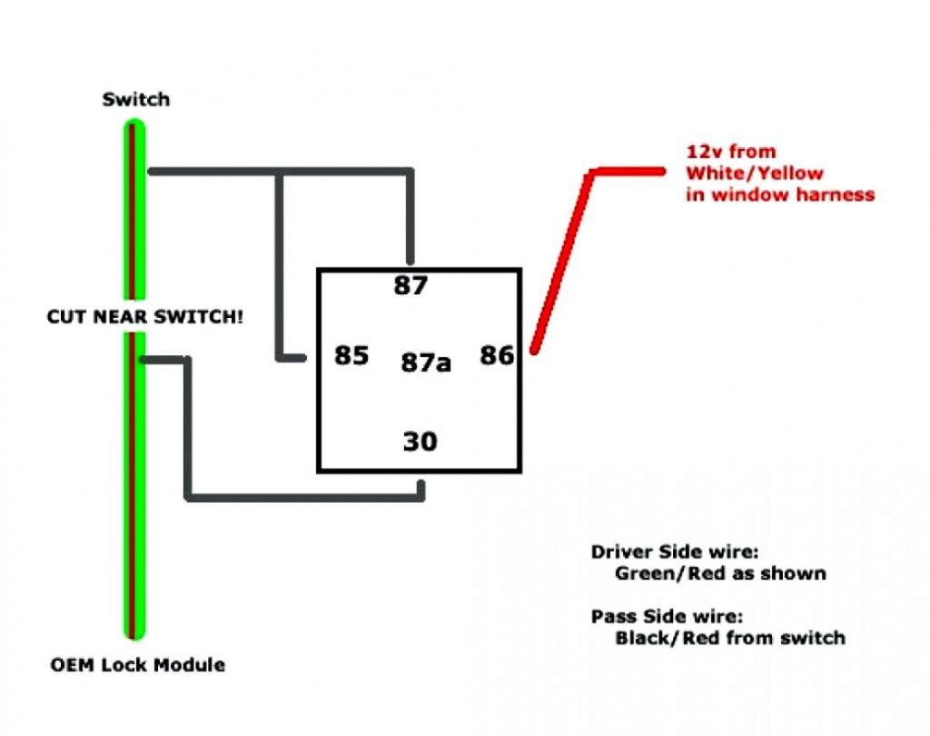
The two most common ways to wire a 5 pin relay is with a positive trig. **PARTS LIST IN DESCRIPTION BELOW**5 pin relay wiring can be done many different ways.
How To Wire A 5 Prong Relay
The relay contacts open to their normal state and stop the current flow to the light. Once you let off of the STOP button the circuit is back to it's normal state with L1 waiting for the START button to be depressed. There you have it. A relay circuit. Now these diagrams are known as relay logic or ladder diagrams.

120 Volt Relay Wiring Diagram Free Wiring Diagram
QUICK TIP: This is a portion of my larger "Relays Explained" video. In this quick tip we look at how to wire a 12V Automotive Relay.See the full video here:.

Relay Wiring Diagram and Function Explained ETechnoG
Relay Wiring Diagram | Relay Connection | Relay Working Principle |A Relay is an electromechanical device that can be used to make or break an electrical con.

5 Pin Relay Wiring Diagram Use Of Relay
A relay wire diagram is an illustration of the wiring layout for a relay. It shows the components of the circuit as simplified shapes and the power and signal connections between them. A relay has a number of terminals, including a coil that gets energized when current is applied.
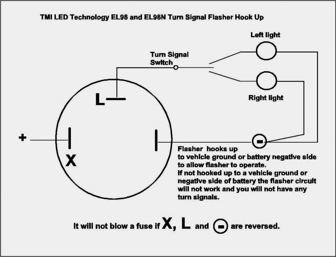
3 Pin Electronic Flasher Relay Wiring Diagram Wiring Diagram and
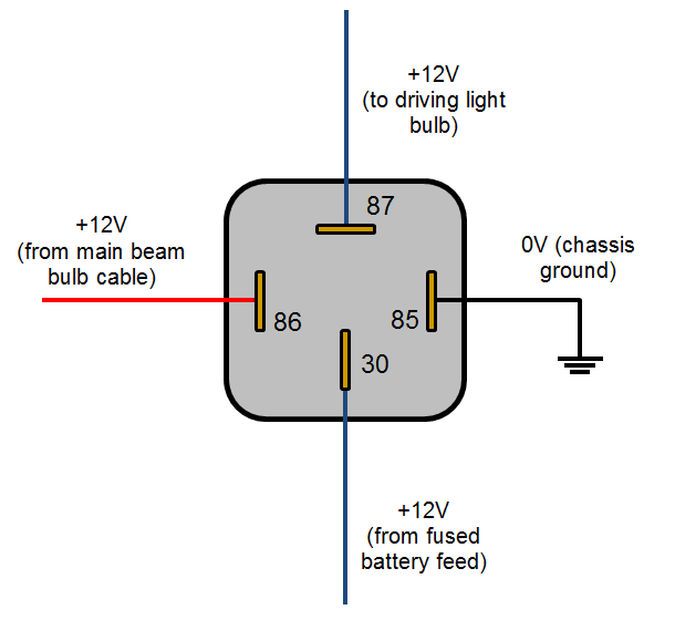
Pin no 1: Usually, pin number 1 is a coil (+/-). Normally, the voltage at which the relay coil is turned on is the operating volt of the relay. The amount of value given in the coil is taken into account and the connection is given with the help of the resistor and the capacitor. Normally, no positive or negative of the relay is specified.

12+ 6 Pin Flasher Relay Wiring Diagram Robhosking Diagram
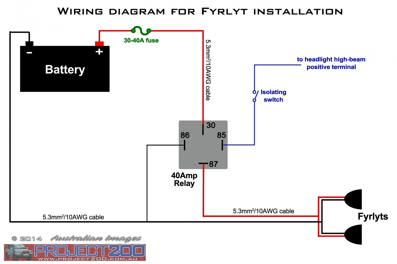
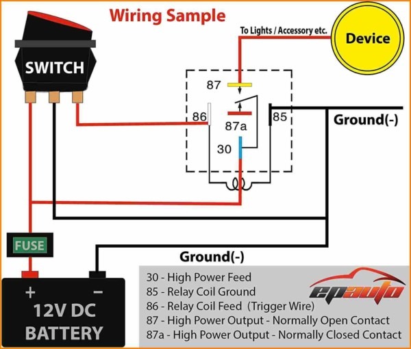
This diagram shows the number and locations of each pin so that you can ensure you're attaching the relevant wire to the correct pin. Browse All Relays How to Wire a 4-Pin Car Relay A 4-pin relay is a simple structured relay. The pin numbers on a 4-pin relay are 85, 86, 87 and 30.

Siemens Overload Relay Wiring Diagram Free Wiring Diagram
Published on: June 17, 2022 7 min read Contents By definition, a relay is an electricity-operated switch. It is used in electronic circuits to regulate and control multiple operations. With the help of a relay, you can control a high current circuit via the setup of a low current circuit.

120 Volt Relay Wiring Diagram Free Wiring Diagram
Select a relay diagram or choose from the list below. (76 relay diagrams available) Relay Wiring Diagrams (Last Updated: 5/4/2020) 1 Connecting Additional Devices to the Remote Turn On Wire 2 Constant to Momentary Output - Negative Input/Negative Output 3 Constant to Momentary Output - Negative Input/Positive Output 4